|
Item |
Performance Parameters |
|||
|
Model Series |
ADL200W |
ADL400W |
||
|
Measurement |
Grid |
Single-phase |
Three-phase four-wire |
|
|
Voltage |
Nominal voltage |
230V |
3×230/400V |
|
|
Input Range |
0.8Unom ~ 1.2Unom |
|||
|
Overload |
1.2 times rating (continuous)
2 times the rating for 1 second
|
|||
|
Power consumption |
<2w, <10VA |
|||
|
Accuracy class |
Error ±0.5% |
|||
|
Current |
Minimum current |
0.3A |
||
|
Transitional current |
1.5A |
|||
|
Basic current |
30A |
|||
|
Maxinum current |
D16:Imax = 120A |
|||
|
Short-term overcurrent |
30 times the maximum current for 20ms |
|||
|
Power consumption |
<1W, <1VA |
|||
|
Accuracy class |
Error ±0.5% |
|||
|
Power |
Active, reactive, apparent power, error ±1.0℅ |
|||
|
Grid frequency |
50Hz, error ±0.5% |
|||
|
Response rate |
50ms (voltage, current, power) |
|||
|
Installation category |
CAT III |
|||
|
Overvoltage level |
OVC III |
|||
|
Metering |
Active electric energy |
Class 1or B |
||
|
Electromagnetic Compatibility |
E2 |
|||
|
Security |
Power frequency withstand voltage |
Between communication and signal input, AC3kV 1min |
||
|
Insulation resistance |
Input and output terminals to casing >100MΩ |
|||
|
Communication |
RS485 interface |
Modbus RTU protocol; addr:1~ 247;Baud rate:1200bps-38400bps |
||
|
Wi-Fi |
Protocols: Modbus-TCP, Http, etc. Operating frequency band: 2.4GHz |
|||
|
Environment |
Operating temperature range |
-25℃~+55℃ |
||
|
Operating temperature range |
-40℃~+70℃ |
|||
|
Storage temperature |
-40℃~+85℃ |
|||
|
Relative humidity |
≤95% (without condensation)
"Not suitable for damp environments" |
|||
|
Altitude |
≤2000m |
|||
|
IP rating |
IP20 on terminal strip without protective housing and IP51 in protective housing, per IEC 60529 |
|||
|
Pollution Degree |
II |
|||
|
UC Degree |
III |
|||
|
Installation environment |
Indoor use |
|||
|
Protect Degree |
Class II (Double Insulation) |
|||
|
Usage Environment |
Cabinet mounted(The outer shell cannot be touched) |
|||
|
Usage Environment |
M1 |
|||
|
Transformer Safety characteristics |
Insulation resistance: greater than 1000 MΩ under normal conditions;
Electric strength resistance: It can withstand 4000V, 50Hz power frequency for 1 minute;
Flame retardancy: Conforms to UL94-V0 level; |
|||
|
Reference Standard |
EN IEC 61010-1:2010 Safety requirements for electrical equipment for measurement, control, and laboratory use - Part 1: General requirements
EN IEC 61010-2-030:2010 Safety requirements for electrical equipment for measurement, control, and laboratory use - Part 2-030: Particular requirements for equipment having testing or measuring circuits
EN IEC 61326-1:2021 Electrical equipment for measurement, control, and laboratory use - EMC requirements - Part 1: General requirements
EN IEC 61326-2-1:2021 Electrical equipment for measurement, control, and laboratory use - EMC requirements - Part 2-1: Particular requirements for electromagnetic compatibility testing for electrical equipment for measurement, control, and laboratory use
EN 50470-3 Electricity metering equipment (a.c.) - Part 3: Particular requirements - Static meters for active energy (class indexes A, B and C) |
|||
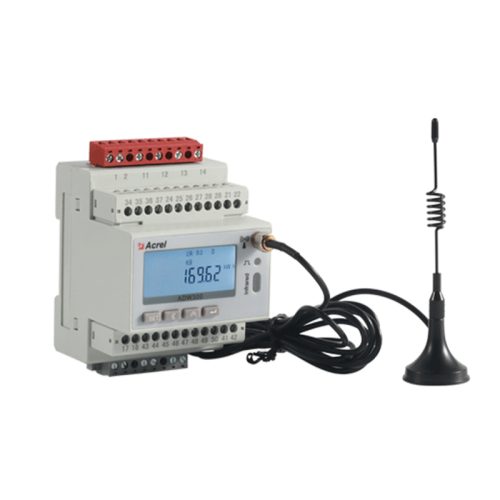
ADL200W-CT Series Single Phase Dual Circuits Electric Energy Meter With External CT
● Single-phase: 230V
● 120A
● RS485(MODBUS-RTU)
● Set parameters
● LCD display
● kWh Class 0.5
● DIN 35 mm
- Fast And Safe Logistics
- Sample Available